Industrial Technology | Experts in Outdoor Enclosures and Thermal Management Solutions
R & D | Production | Sales
You are here: Home » Products » Outdoor Cabinets and Enclosures » Accessories » Embedded Rectifier Power Supply System for Telecom

Embedded Rectifier Power Supply System for Telecom

E4860 System configuration
 
  • Two 4830 rectifier modules
  • 1 monitoring module
  • E4860 output part

DC power distribution: 1 channel (battery) and 1 channel (load)
  • E4860

  • CYTECH

Availability:
facebook sharing button
twitter sharing button
line sharing button
wechat sharing button
linkedin sharing button
pinterest sharing button
whatsapp sharing button
sharethis sharing button

Product Description


Product introduction video


Certificate


E4860 Technical Performance


E4860 is suitable for power supply of small program-controlled switchboard, access network, transmission equipment, mobile communication, satellite communication ground station, microwave communication, and other communication equipment.


Basic working principle


When the system power supply is normal, various parameters of the rectifier module and the power distribution unit are controlled by the monitoring module and work according to the preset parameters or user commands. If there is a mains failure, the system will be powered by the battery. With the discharge of the battery, the voltage of the battery begins to drop. When the battery voltage is lower than the alarm valve 46V(settable) on the position machine, the monitoring module will report an alarm signal. If it is lower than 43V, the load output will be directly turned off, and the whole machine will not work. When the external mains supply is restored, the system resumes normal operation (the above monitoring data is the default value of the system, and the user can set it again through the background).

If the operating ambient temperature of the power supply system is ≥ 55 ℃, Power systems need to reduce power output.


Performance Index


Input
AC Input
Rated input voltage 220VAC

Input voltage range

90 ~ 280VAC
Maximum input current 30 A
Frequency 50Hz; 45~63HZ
Input power factor ≥ 0.98
Battery Input The positive and negative poles of the battery pack are connected in parallel with the DC output of the rectifier module (with the same polarity), and work in floating charge or equalized charge state.
Working efficiency ≥ 91% (220Vac input)
≥ 87% (110Vac input)
Output
DC Output

Standard voltage

54VDC


Voltage adjustable range

42V ~ 58V

Current (full configuration)

60 A (176 ~ 290 VAC)

33A (151~175VAC)
22A (90~150VA)
DC output

1 channel (load); 1 channel (battery)

Noise

Telephone weighing noise

≤2mV
Broadband noise voltage

≤100mV (3.4KHz~150KHz)

≤30mV (150KHz~30MHz)
Peak-to-peak noise voltag ≤ 200mV (within 20 MHz)
Power supply system

Voltage stabilization accurac

≤±1%

Load regulation rate

≤±1%

Source regulation rate

≤±1%

Other characteristics

Dynamic response overshoot amplitude

≤ ± 5%

Dynamic response recovery time

≥ 10ms
Current unbalance

≤ ± 5%

Insulation

Resistance

between DC part, AC part and enclosures ≥ 10 MΩ (test voltage 500Vdc)

Leakage current < 3.5mA

Strength

Apply 50Hz 2500Vac AC voltage to the AC input and DC output parts, with leakage current≤10mA, and no breakdown and flashover in one minute;

The AC part and the enclosure are applied with 50Hz 2500Vac AC voltage , the leakage current is≤10mA, and there is no breakdown and flashover in one minute;
Apply 50Hz 1000Vac AC voltage between the DC output and the enclosure, with leakage current≤10 mA, and no flashover in one minute.


Protection Function


Item

Unit

Yes/No

Minimum

Typical

Maximum

Recovery characteristics

Input overvoltage alarm

Vac

Yes

250

260

270

The recovery difference is 10 ± 5V

Input undervoltage alarm

Vac

Yes

130

140

150

Input overvoltage protection

Vac

Yes

300


315

Self-recovery, recovery difference 10 ± 5V

Input undervoltage protection

Vac

Yes

75


85

Output overvoltage alarm

V

Yes

58


59

Recovery difference: 1V

Output undervoltage alarm

V

Yes

46.5

47

47.5

Recovery difference: 1V

Output overvoltage protection

V

Yes

59


60

Not self-recoverable

Battery power-down protection

V

Yes

42.5

43

43.5

Recovery difference 2.5-3 V

High ambient temperature alarm

Yes

45

50

55

Recovery difference 3 ℃

Low ambient temperature alarm

Yes

-15

-10

-5

Short circuit protection

A

Yes

Can be short-circuited for a long time; Hiccup works after short circuit is detected. If the module output is still short circuit after hiccup for 5min, shut down.


Mechanical Characteristics


Cooling mode: forced cooling by fan

System size (L × D × H): 482 mm × 295 mm × 44.45 mm

Total weight of system: ≤ 7.3Kg (with module)

Installation dimension description: (depth excluding handle length 20mm; total depth: 260mm + 20mm + 14.7mm = 295 mm


Requirements for Environmental Conditions

Working temperature: E4860 embedded power supply system is powered on when the temperature is less than -40 ℃ (but does not supply to the load), and works normally at -40 ℃ ~ + 55 ℃; When the temperature is higher than 55 ℃, the power supply system is derated.

Relative humidity: 10 ~ 90%

Atmospheric pressure: 70 ~ 106KPa

Altitude: 0 ~ 3000m


Installation


System Installation


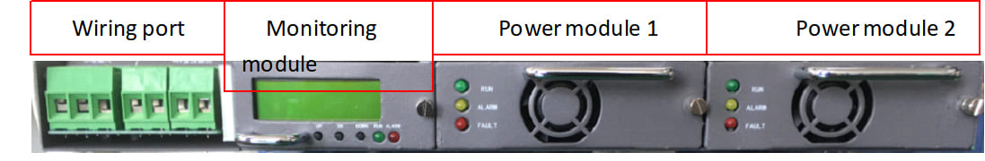
When the E4860 system is packaged and transported, the monitoring module and all rectifier modules have been installed on the system mainframe, as shown in the figure (the system configuration capacity is 60A, that is, it consists of two 4830 rectifier modules and one monitoring module).


E4860 Main Chassis (Front View)


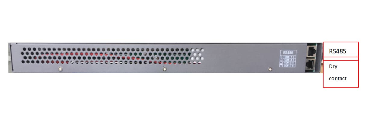
E4860 Main Chassis (Rear View) 


Electrical connection between the main cabinet and the outside


Description of electrical connection


The main cabinet make its electrical connection with the outside through its system interface board. Interface position of the system interface board is shown in the figure.


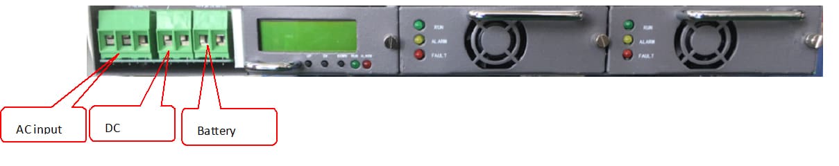
System interface board interface position diagram of E4860 power supply


Description of wiring terminals connection:

  • AC input interface: L (Line), N (Neutral), PE (ground);

  • From left to right: output cathode, output anode, battery anode, battery cathode,


Electrical connection process

The electrical connection between the main cabinet and the external equipment includes: connection of AC input, connection of DC output and storage battery, connection of communication wire, and connection of grounding wire. As will be described in detail below, the key point of electrical connection is safety and reliability.


(1) System AC lead-in connection

The AC lead-in of E4860 system is terminal block, which is located on the front panel of the system; The AC connecting wire can be connected directly.


Notice

1. The AC lead-in wire is a high-voltage working wire. During operation, it is necessary to ensure that the AC input is powered off. During operation, temporary prohibition signs shall be added to the switches that are not allowed to be used.

2. AC wire terminal contacts and other unnecessary exposed places shall be fully insulated.

3. Must be grounded before power on.


(2) System DC working wire connection


Load wire connection

The load terminals of the E4860 system are the "LOAD + and LOAD-" terminals, which are located on the front panel of the system and can be wired directly.

A. The selection and routing of the load wire shall be based on the engineering design requirements, and the appropriate cable shall be selected.

B. Connect one end of the positive connecting wire to the "LOAD +" terminal on the front panel of the system;

C. Connect one end of the negative connecting wire to the "LOAD-" end on the front panel of the system;


Battery cable connection

The wiring between the system and the battery is terminal block, marked with "BAT +" and "BAT-", which is used to connect the battery. The connecting wire can be directly connected to the terminal block. The following is a detailed description of the battery connection process.

A. Prepare the positive and negative connecting wires (including connecting the terminal and positive or negative identification).

B. Tie up the battery cable.

C. Connect one end of the positive connecting wire to the BAT + terminal on the rear panel of the system;

D. Connect one end of the negative connecting wire to the BAT- terminal on the rear panel of the system;


(3) Ground wire installation

Protective grounding connection: connect the chassis grounding point of the system main chassis to the external grounding busbar with a wire of more than 6mm2.


(4) Installation of communication wire

The communication wire interface RS485 of the E4860 system is located on the rear panel of the system. RS485 is a communication port for communication with the position machine.

RS485 communication mode:

A. Connect one end of the communication wire to RS485 on the rear panel of E4860.

B, connecting the other end of the communication wire to RS485 of the position machine, wherein the positive terminal and the negative terminal of RS485 respectively correspond to the positive terminal and the negative terminal of RS485.


Installation inspection


(1) Contents: check the installation stability of the frame body and each assembly units.

(2) AC lead-in and power distribution inspection: whether the AC wire chromatogram is standardized, whether the original wiring of the rack is loose, and whether the safety signs of the AC power distribution part are complete. Check the AC wiring and the use of wires according to the design data.

(3) Check the DC output and battery connection area, number and wire sequence polarity, check the stability of cable connection area, check the correctness and reliability of busbar connection, and re-check the battery connection polarity and sequence.

(4) Set all switches at the off position.


Installation instructions of monitoring module and rectifier module


The installation position of the monitoring module and the rectifier module on the E4860 system main chassis is shown in the figure.


Schematic Diagram of Installation Position of Components on E4860 Main Chassis


1. Two 4830 rectifier module slots.

2. One monitoring module interface slot.

The panels of the monitoring module and the rectifier module are provided with handles. When inserting into the main chassis, hold the handle with one hand and hold up the component with the other hand, and slowly push it into the corresponding slot until the connecting terminal of the rear panel of the component is inserted into the corresponding socket of the motherboard of the main chassis system. Finally, tighten the fixing screw on the upper side of the panel on the main chassis, and the installation is completed. When each component exits the main chassis, loosen the fixing screws on the upper side of the panel, hold the handle tightly, and slowly withdraw the component from the corresponding slot.


Notice

The 4830 module has the function of plug and play, but the indicator lights on the module panel must all be off before the module is inserted.


Options

More Optionals of Embedded Rectifier Power Supply System


Model

Maximum output powe

Input voltage range

Output voltage

Output current Rectifiers
E4860 3KW 85-300Vac 53.5V 60A
RM4850*2(Fully equipped2PCS)

5U-4815

9KW

85-300Vac

53.5V 150A RM4850*3(Fully equipped4PCS)

5U-48200

12KW

85-300Vac

53.5V

200A

RM4850*4(Fully equipped4PCS)

6U-48300

18KW

85-300Vac 53.5V 300A RM4850*6(Fully equipped8PCS)
7U-48450

27KW

85-300Vac 53.5V

450A

RM4850*9(Fully equipped12PCS)


Optional  Accessories


The following accessories are available for optional ordering.


Item Technical parameter   Picture
EMS 19 inch environment monitoring unit 1U; 

DC48V, support RS232,RS485, SNMP,TCP/IP communication protocol.                

1× smoke sensor,                

1× water sensor,                

1× temperature sensor,                

1× door sensor.        


Environmental monitoring system is a comprehensive network of devices and technologies designed to track and assess various aspects of the environment. This system plays a crucial role in gathering data to understand environmental conditions, detect changes, and manage natural resources.                


OUTDOOR ENCLOSURE EMS


Fire Extinguisher

Hot aerosol fire extinguishing device is a new, efficient and environment-friendly fire fighting product with Vanguard International Semiconductor Corporation level, which is the first in China. It is a high-tech green fire protection product that benefits humanity, born under the background of the International Montreal Agreement and China's increased awareness of environmental protection. It is an ideal substitute for halon fire extinguishing devices and is suitable for relatively enclosed spaces such as distribution cabinets.


Electric or hot start:                

Hot start temperature ≥170℃;                

Electric start temperature ≥700mA.          


Outdoor Enclosure Fire Extinguisher


Wiring type PDU

AC input:63A/2P*2 with interlock;                

AC/SPD:30-60KA/2P*1;                

AC output:63A/1P*1,32A/1P*1,16A/1P*3,3 holes Maintenance socket*1              


Integrated PDU Can be customized according to customer requirements.

Integrated PDU

Rectifier AC220V/110V transfer to DC48V, Connect the battery as a backup power,also can be customized according to customer requirements.  

Rectifier


ODF

Optic Distribution Frame (ODF) is a critical component in a fiber optic network infrastructure. It serves as a centralized point for the termination, organization, and distribution of fiber optic cables. The primary purpose of a distribution frame is to facilitate efficient and organized connectivity, making it easier to manage, troubleshoot, and expand the network.          


Function:                

1)Termination Point;                

2)Organization and Management;                

3)Splicing Trays;                

4)Labeling and Documentation;                

5)Security and Protection;                

6)Scalability;                


Can be customized according to customer requirements.             


ODF


Backup battery Can be lithium battery or lead acid battery.  


Maintenance


Monitoring Module Maintenance


(1) Cause analysis and maintenance of communication interruption

  • Setting reason: the monitoring unit is inconsistent with the position machine;

    Maintenance: reset the address of the monitoring unit through the background.

  • Monitoring module CPU circuit failure or secondary rectifier module circuit failure.

    Maintenance: notify the manufacturer for maintenance.


(2) If the reported data is incorrect (including analog value and switching value) and remains unchanged, or the control status is inconsistent with the issued command, or the parameter setting is inconsistent with the actual execution, it may be due to the following reasons:

  • The input signal is incorrect;

  • The input circuit is damaged;

  • Rectifier module failure.

Maintenance: notify the manufacturer for maintenance.


Indication


Rectifier Module Alarm Signal Indication


(1) When the power module operates normally, the green light is on; Otherwise, it will be off. (The green light is off in case of mains failure and no output of the module.


(2) When the power module operates normally, the yellow light is off. Otherwise, there will be temperature pre-alarm, automatic derating, current limiting and fan pre-alarm, and the yellow light will be on.


(3) When the power module operates normally, the red light is off. The red light is on when there are cases of power module failure, such as output overvoltage shutdown, fan failure, over temperature shutdown, remote shutdown or other internal reasons.


LED signal indication

LED status

Module alarm status

Color of the indicator light

Normal state

Abnormal state

Cause of abnormality

Operation indicator

Green

On

Off

When the red light is on, it goes out.

See the table below when the yellow light is on.

Protection indicator

Yellow

Off

On

When the power supply module has recoverable protection, the module ALARM is always on, otherwise, the yellow light flashes when the communication is interrupted;

OTP (from ambient temperature above 65 ℃ to module over-temperature shutdown), input over-voltage and under-voltage are valid and over-current, the ALARM is valid.

Hibernation shutdown (during hibernation shutdown, the module only lights up the protection indicator, and the module won’t report an alarm.)

Fault indicator

Red

Off

On

If there is an unrecoverable fault inside the module, the module FAULT is always on, when PS-enable is normal, Vo-OV, fan fault (single or double fan fault), output short circuit and no output occur, FAULT is valid.


(4) Precautions for use and maintenance of rectifier module


  • If the red lamp (FAULT) on the front panel of the rectifier module is always on during the normal period, it indicates that the rectifier module has a working fault. At this time, the module should be removed from the system and prepared for maintenance. If the rectifier module is damaged, please contact the manufacturer. It is forbidden to disassemble the rectifier module by non-professional personnel from the factory without permission.


  • Allow electric hot plug and play

    a. When the whole module needs to be removed from operation, unscrew the fastening screw, hold the handle, and pull it out without turning off the AC power supply. In this way, in the power supply system composed of multiple modules, we can make sure the whole power supply system does not need to be powered off when a rectifier module needs to be removed for maintenance, and ensure the normal operation of the power supply system.

    b. When the electrical interface of the rectifier module is connected to the power supply system, it must be ensured that the indicator light on the front panel of the rectifier module is off before the rectifier module can be inserted.


Previous: 
Next: 

Consult Your Cytech Outdoor Cabinet And Thermal Management Experts

Consult Your Cytech Experts
PROUDCTS
SUPPORT
QUICK LINKS
CONTACT US
    info@cytech.org.cn
   +86 13775296911
   weidun2013
    #5 Fuling Road, Zhonglou district, Changzhou, Jiangsu, China
COPYRIGHT © 2023 CHANGZHOU CHEN TONG YUAN COMMUNICATION EQUIPMENT CO.;LTD ALL RIGHTS RESERVED.