Overview
A typical communication base station combines a cabinet and a pole. The cabinet houses critical components like main base station equipment, transmission equipment, power supply systems, and battery banks. Meanwhile, the pole serves as a mounting point for antennas, Remote Radio Units (RRUs), and other equipment, often resembling a “candied hawthorn stick” in its configuration.
For setups with a dedicated communication equipment room, these devices are arranged either on integrated racks or standalone cabinets, forming a complete, functional system.
Key Components of Base Stations
1. Main Base Station Equipment
Often referred to as the brain center, this includes:
Baseband Unit (BBU): Handles baseband signal processing.
Remote Radio Unit (RRU): Converts signals to radio frequencies for transmission.
Active Antenna Unit (AAU): Integrates RRU and antenna for 5G-era efficiency.
2. Power Supply System
This acts as the “blood supply” of the base station, ensuring uninterrupted power. It includes:
AC distribution box: Distributes mains power and offers surge protection.
Switch-mode power supply: Converts and stabilizes power while managing DC output.
Battery banks: Serve as backup power to keep systems running during outages.
3. Transmission Equipment
Key for connecting base stations into a network, this system ensures smooth communication. It becomes a top priority during power outages to maintain data flow.
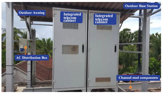
Outdoor Base Station Features
Outdoor base stations integrate all essential systems into a single Integrated Cabinet, designed to endure harsh conditions like direct sunlight, rain, and extreme temperatures. These units protect the equipment while ensuring efficient functionality.
Communication Tower: Elevating Connectivity
Towers are crucial for mounting antennas at high elevations, ensuring wide signal reach. Key components include:
Tower base: The foundation.
Tower frame: Includes braces, ladders, and platforms for support and accessibility.
Antenna support: Ensures precise placement and stability of antennas.
About Networking in Mobile Communication Systems
Mobile communication networking is an essential topic when delving into the field of communication design.
To understand the intricate world of mobile networks, it's crucial to grasp the role of base stations within the larger telecommunications network. These stations act as “business trackers,” small yet robust, and form an independent, self-sustaining system. Their role, much like a strategy game, involves ensuring "blood supplies" (power) and "mana replenishments" (signal transmission) to maintain the seamless delivery of radio waves.
1. Base Stations: The Business Trackers of Telecommunications
In the vast telecommunications network, communication base stations play a frontline role. Positioned closest to end users, they serve as gateways for processing customer requests and managing data flow. In the words of "Interesting Communication Engineering Drawings," these stations act like “business trackers,” always vigilant to:
Respond to customer needs via the air interface.
Request additional “firepower” (data and signal strength) from data centers.
Relay information across long distances.
This role places them at the critical intersection of user terminals and data centers, making them indispensable in the network.
2. Compact Yet Complete Systems
Base stations, while small in structure, are equipped with everything necessary to operate independently. They ensure:
Protection against environmental factors like wind, rain, and lightning.
Uninterrupted power supply through robust systems and backup solutions.
Efficient signal transmission to connect users to the broader network.
Antenna frames for seamless radio wave emission.
These components create a harmonious and self-sufficient system, reflecting a unique beauty in their engineering.
3. The Game of Blood Supply and Mana Replenishment
Operating a base station is akin to managing resources in a strategic game. Each system has a specific role:
Power Supply Equipment: Provides the "blood" necessary to keep the system running.
Transmission Equipment: Replenishes "mana" to ensure uninterrupted data flow.
Main Base Station Equipment: The “hero” of the setup that orchestrates the overall operation.
The coordinated effort of these elements ensures that every connection, from a simple phone call to high-speed data transmission, functions smoothly and reliably.
Visual Representation
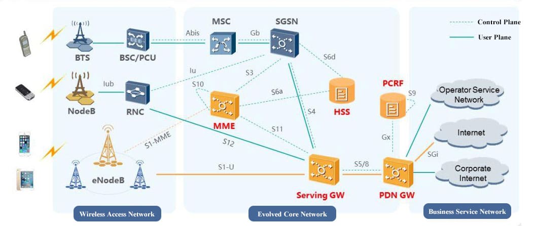
1. Base Station’s Role in the Network
The base station, positioned between users and data centers, is the first responder to user requests. It relays signals efficiently, ensuring users stay connected.
2.The Complete System of a Base Station
This image highlights the compact but comprehensive nature of base stations, showcasing their integration of protective enclosures, power systems, and antennas.
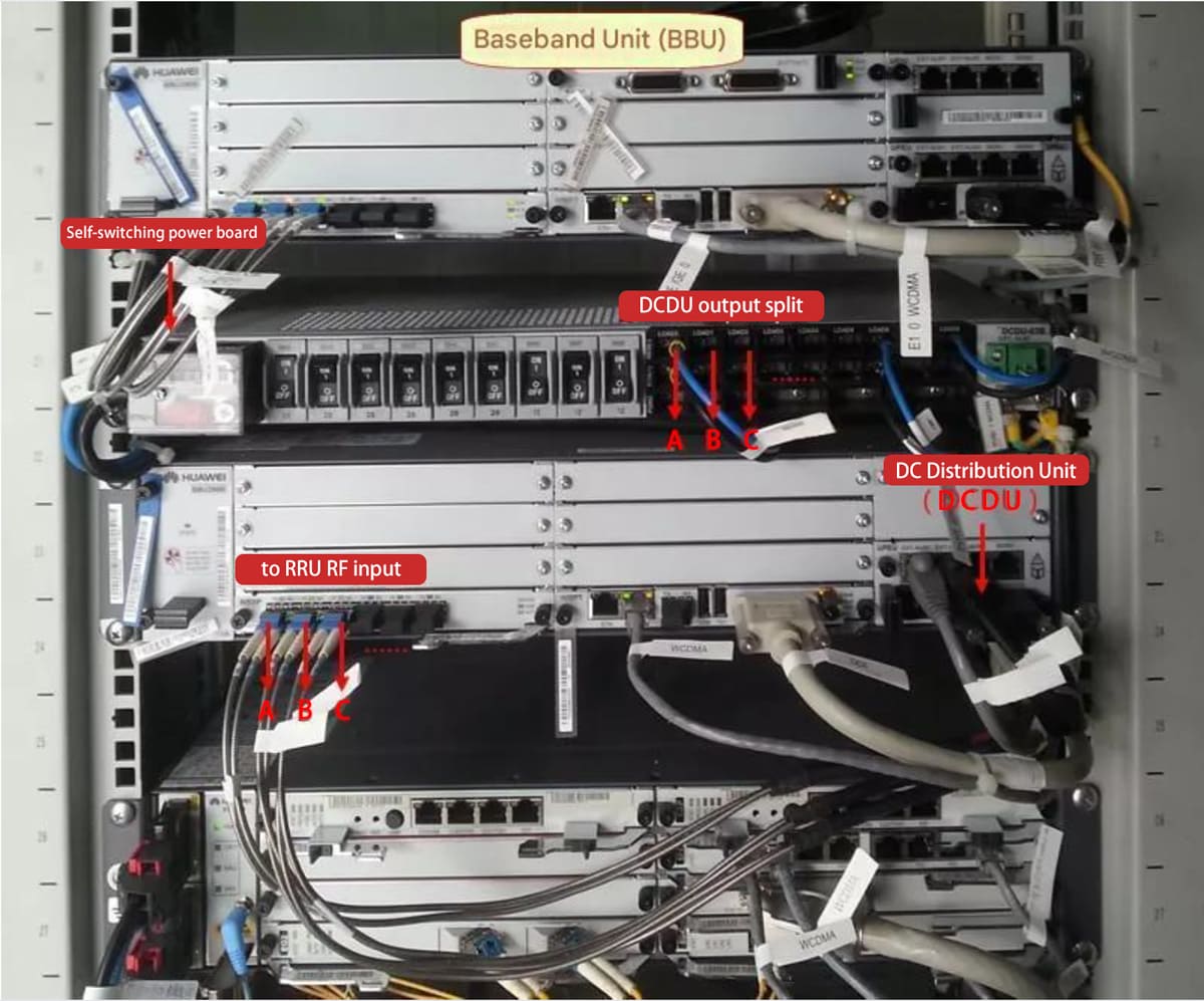
3. Power and Transmission Systems at Work
Here, you can observe how power supply and transmission systems collaborate to support the “brain” of the base station, ensuring seamless functionality.
Brain Center: Main Base Station Equipment
At the heart of mobile communication networks lies the main base station equipment.
Central to this setup are three critical components—BBU (Baseband Unit), RRU (Remote Radio Unit), and AAU (Active Antenna Unit)—terms you’ll frequently encounter in this field. While these acronyms might sound like technical jargon to outsiders, understanding their roles reveals the intricate orchestration behind modern telecommunications.
1. The Core Layout: Main Base Station Equipment Connection Diagram
The connection diagram provides a clear overview of how the main base station equipment operates within the network. Surrounding this central "brain" are the “Four Guardians” that ensure seamless functionality:
Power Supply: Provides a steady and uninterrupted energy source to keep the equipment operational.
Transmission Connection: Extends communication links across long distances, enabling seamless connectivity beyond single points.
Lightning Protection and Grounding: Safeguards the tall iron towers from lightning strikes, a common risk due to their height.
Signal Transmission: Converts the processed signals into radio waves for user communication.
Understanding this setup demystifies the numerous cables and connections, simplifying the perceived complexity of the system.

2. Baseband Unit (BBU): The Signal Processor
The BBU is a key element of the base station's architecture. Unlike the large cabinet setups of the past, modern BBUs are compact and resemble distributed devices, similar in size to DVD players.
Function: Processes baseband signals, which are low-frequency signals in their raw, unmodulated state.
Workflow: After processing, the BBU sends these baseband signals to the RRU for modulation into radio waves.
Power Handling: Power distribution within the system is managed by the Power Distribution Unit (PDU).
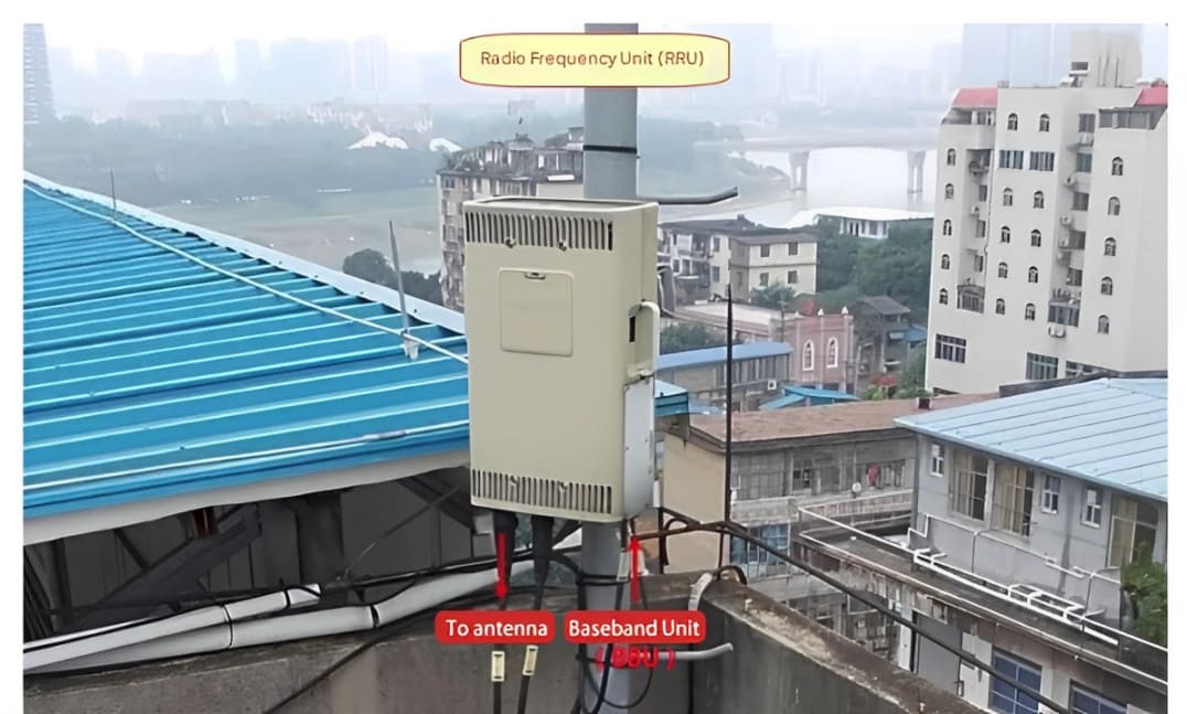
3. Remote Radio Unit (RRU): The Signal Modulator
The RRU is typically mounted on the communication tower, positioned just below the antenna.
Function: Modulates low-frequency signals from the BBU into high-frequency signals.
Final Stage: These high-frequency signals are transmitted through the antenna as radio waves, completing the signal journey from base station to user.
By performing radio frequency signal processing, the RRU ensures that users receive high-quality communication.
Blood Supply Pump Station: Power Supply Equipment
The base station power system serves as a continuous "blood supply pump station," responsible for AC/DC conversion, filtering, voltage stabilization, and backup power. Its purpose is to ensure the uninterrupted operation of base station equipment.
This system comprises various components such as AC distribution boxes, generator switch boxes, switch-mode power supplies, and battery banks, each playing a vital role in maintaining seamless power flow.
1. Power Source: Mains Power Input
Where does the electricity for communication base stations come from? It starts from large power plants and flows through substations, distribution stations, and along transmission lines, transforming along the way from towering iron pylons to smaller H-poles, eventually reaching its destination.
For base stations, this journey culminates in three-phase AC power being connected to the system. This is referred to as mains power input, which represents the final stage of the power production and supply chain.
2. Power Distribution and Protection
When mains power enters the equipment room, it undergoes a series of processes to ensure reliable and safe operation:
AC Power Distribution: The incoming AC power passes through the AC distribution box for secondary distribution and surge protection.
Switch-Mode Power Supply: This critical component performs rectification, filtering, and voltage stabilization, converting AC power into DC power.
DC Power Output: The processed DC power is supplied to main base station equipment, transmission devices, and battery systems.
In addition, grounding protection is implemented for all critical equipment, safeguarding against electrical faults.
3. Key Components of the Power System
AC Distribution Box
Role: This wall-mounted box is the first checkpoint for incoming mains power. It handles secondary AC distribution and offers protection against lightning and power surges.
Placement: Usually positioned at the side of the equipment room.
Switch-Mode Power Supply
Core Functionality: Often referred to as the "core" of the power system, this device handles AC/DC distribution, rectification, filtering, and remote monitoring.
Output: Supplies clean and stable DC power to crucial equipment.
Battery Bank
Backup Power: In the event of a power failure, battery banks act as silent guardians, providing backup power and energy storage for base station equipment.
Lithium-Iron Phosphate Batteries: Compact alternatives often used in outdoor communication cabinets.
The base station power system is the backbone of communication infrastructure, ensuring uninterrupted operations through its robust design and redundancy features. From mains power input to the final DC output, every component contributes to maintaining the "lifeblood" of telecommunications.
Angel's Wings: The Antenna Feeder System
Radio waves are recognized as the most ethereal concepts because they are invisibly incorporated and beyond physical touch yet radio waves act as the ‘messengers’ for sending information.
When an antenna array switches the angle, it unfurls with smooth elegance as a butterfly from its chrysalis. It has wings like an angel To deliver comforting words from loved ones, slowly fades away toward the horizon of the sky.
1. Anatomy of the Antenna Feeder System
Following is a structural representation of the antenna feeder system and it’s constituents.From BBU to RRU to the antenna point, feeders are safely connected and signals are emitted in the most exact manner possible. Feeders and connectors, grounding clamps and feeder clamps act as auxiliary in relation to this process.As for many of the traditional components in base stations, with the development of distributed base station equipment, it is greatly simplified. Furthermore, the wire pigtails are now often single instead of multiple auxiliary materials, much more convenient to be set up.
2. The Magic of Radio Wave Propagation
The following diagram graphically shows the nature of radio wave and how they evolve from point to another as they travel through space.In fact, an antenna can be called a convertor – electricity produces magnetism, and magnetism produces electricity. In the contemporary world, adjustable electrical antenna is prevalent in the urban areas, where the mechanical antennas are still used in the rural areas. They also became merged into one equipment called the Antenna Array Unit (AAU) due to introduction of 5G.The possibilities opening through the remote control of electrically adjustable antennas are revealed below in one of the examples.
3. From Theory to Practice
Even after years of working for the communications industry the specifics of how a wireless signal operates might sometimes seem like a vague memory, those formulas that one learned at school. Yet, the essence remains clear: a perfect antenna then transmits open electromagnetic waves from the closed transmission lines in a vane like the wings of angels flying to their destination.
4. A Celestial Journey
Such a signal as a go-between extends from one end of the earth to the other through the angels to unite people, communities, ideas. To better understand the process they go through, please, follow this set of the videos that presents the process of this smooth transmission in details.
Pillar of the Sky: The Communication Tower
Confining yourself to searching for “towers” constantly you turn around and it is there standing sturdy while butterflies fly—a motionless watchman under the vast blue.
1. Insights from the Tower
Every look at a communication tower, whether after years of work, shows one something new. Every single tower has a story to tell or rather educate the generation and advanced generation of ‘‘communication laborers.” The mere beauty of the roof that creates a breathtaking scenery is unnoticed by the general public and the effort of those construction workers who put it all together.
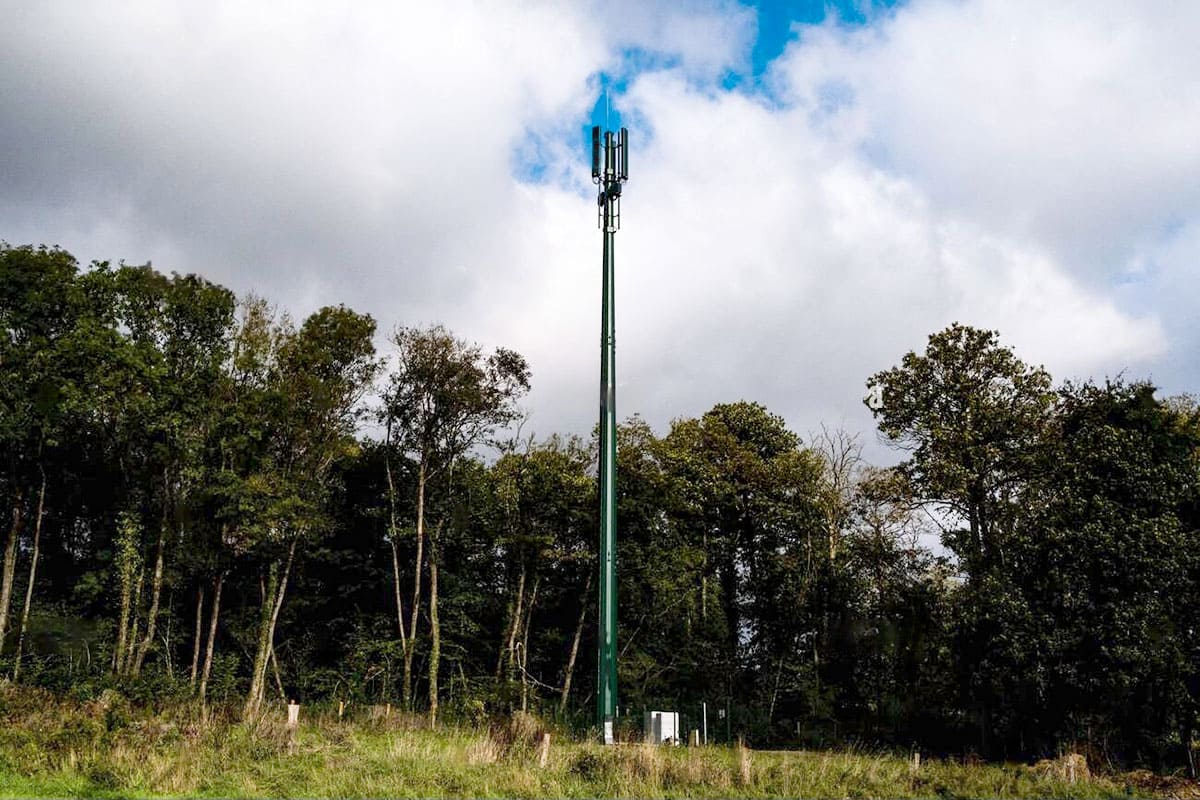
2. The Communication Tower as a Skyborne Pillar
A communication tower is not just an installation; it is a ‘pillar of the sky,’ supporting antennas to certain altitudes that allow coverage of vast radius with radios waves. Here is a picture of a single-pole communication tower, a structure AV that is mostly a series of antennas stretching into the skies.
3. Classification of Communication Towers
Communication towers can thus be classified in the basis of material, geographical height, structural configuration and mechanism of support. Some of the most common types include:
Lattice Towers
Monopole Towers
Guyed Towers
Self-Supporting Towers
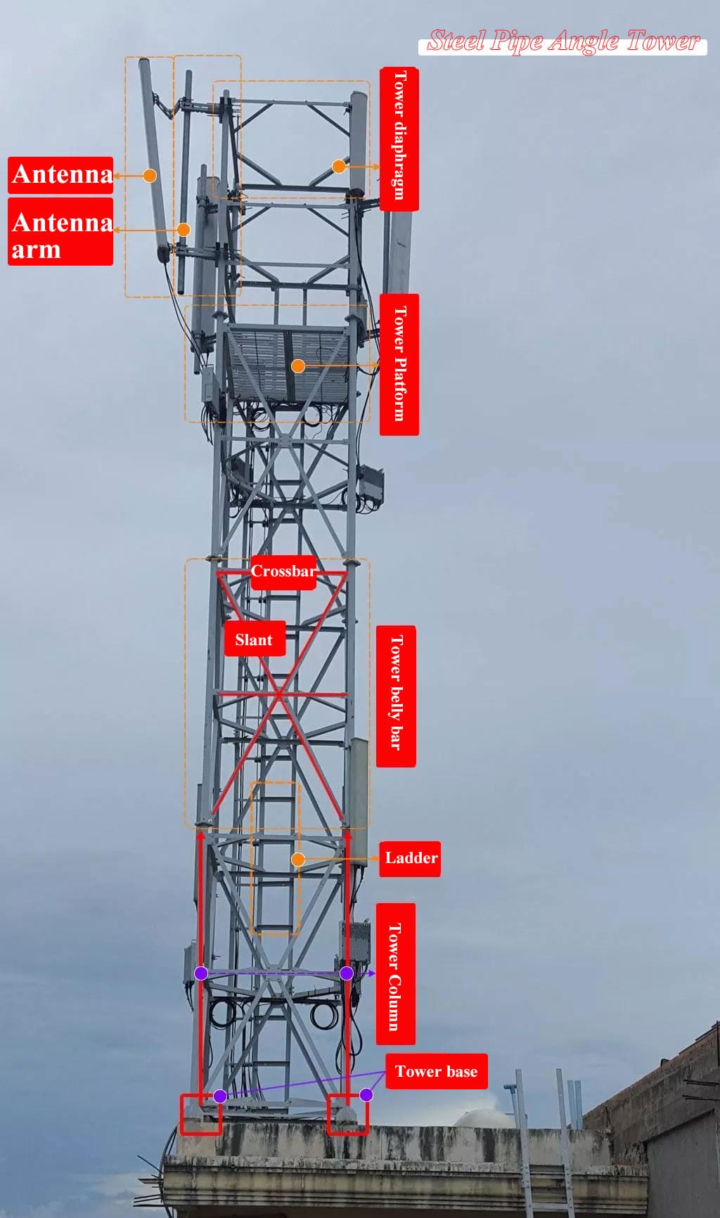
4. Structure of a Communication Tower
The composition of a typical communication tower includes:
Main Materials: Steel or other load-bearing elements.
Web Members and Horizontal Braces: Provide stability and distribute stress.
Auxiliary Rods: Support smaller loads.
Tower Base: Ensures structural integrity and balance.
These components are the "secret codes" for effective communication with industry professionals.
Experience Sharing: Survey and Design for Wireless Communication
"The stone from other hills may serve to polish the jade of this one."
For those involved in wireless surveys and design, the final goal is the construction drawing that guides engineering efforts. Here's a breakdown of effective survey methods:
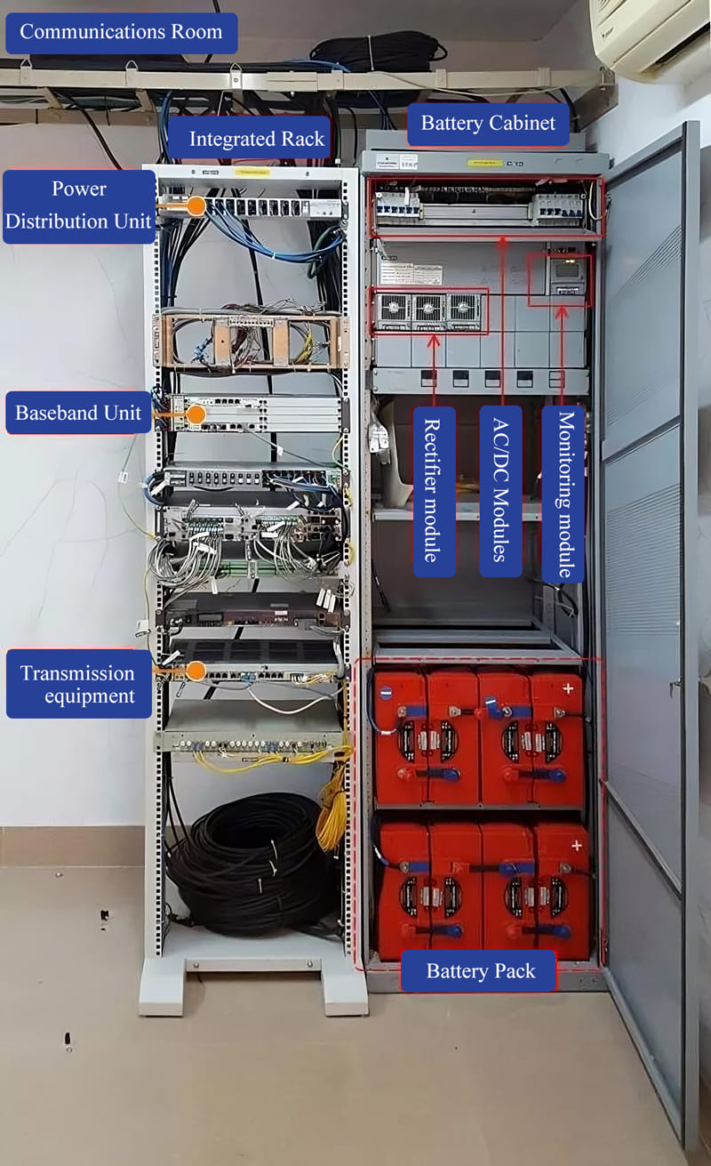
1. Overall Room Perspective
Open the equipment room door and capture a wide-angle view to understand the layout.
This image shows the switch-mode power supply, integrated rack (housing BBU and transmission equipment), battery banks, and cables along the trays.
2. Cabinet Positioning
Stand before the cabinets and capture their arrangement. This helps determine where to place new equipment like the BBU.
3. Module-Level Detail
Open cabinet doors to inspect and photograph each module and unit, focusing on circuit breakers, power usage, and space availability. This helps determine where to connect power for new equipment.
Preparation and Precision
Keeping a checklist and coming up with pre printed templates of the form to be filled helps to streamline work and avoid errors. This method lets you plan and organize, check and verify and make backups of info so as to minimize mistakes and oversights.Through these careful practices, communication towers remain unnoticed as the significant supporting part in the world connectivity puzzle, as the sign of humanity’s achievements and determination.


